
AUDI TFSI ENGINE TECHNOLOGIES
Tfsi engines 20th Aachen Colloquium Automobile and Engine Technology 2011
TFSI Engines from Audi -Innovative Technologies in Current and Future-
Dr. Rainer Wurms, Michael Jung, Dr. Stephan Adam,
Dr. Stefan Dengler, Dr. Thomas Heiduk, Axel Eiser
AUDI AG, Ingolstadt
Summary
Over the last 7 years the turbocharged direct-injection SI engine – designated TFSI
by Audi – has successfully penetrated the market for passenger car SI engines.
Thanks to its many significant advantages, TFSI technology will replace most other
SI engine concepts in the near future, just as TDI technology did in the past.
As the pioneer and technology leader in TFSI, Audi has continually enhanced its
TFSI technology since its first production fitting of a direct turbocharged engine in
Europe and NAR in 2004. In 2011 Audi launched what is already its third generation
of four-cylinder inline TFSI engines onto the market. Once again, this third generation
incorporates many innovative technologies applied to an SI engine for the first time
anywhere in the world.
In addition to the Audi Valvelift System, for the first time the engine has a cylinder
head with integrated exhaust manifold and complete cylinder firing sequence
separation, an electric wastegate actuator, an innovative thermal management
system and a completely new mixture preparation system in order to comply with
future exhaust emission standards.
The presentation details the design and working principle of the new technologies in
the third-generation TFSI engine. It also looks ahead to potential further technology
advances for future SI engines.
1 Introduction
Exhaust gas turbocharging has a long-standing tradition at Audi. Since the initial
launch of a turbocharged petrol engine in 1979, Audi has been continually advancing
its turbocharger technology.
There were two outstanding events, however, which dictated the future of Audi
engines – and ultimately then also of petrol engines in general. Whereas in the
period from 1979 to 1995 Audi turbocharged engines were deployed only in specialist
sports designs and in a few high-end applications, the launch of the four-cylinder
inline 1.8l 5VT in 1995 marked the breakthrough for the turbocharged engine as a
widely accepted standard power unit for passenger cars.
The introduction of TFSI technology in 2004 then saw the beginning of a new era in
petrol engine technology.
2 20th Aachen Colloquium Automobile and Engine Technology 2011
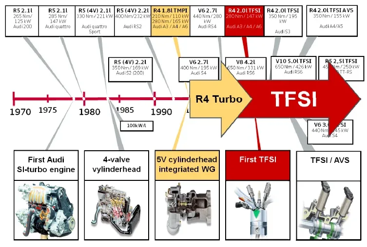
Fig. 1: History of petrol engine turbocharging at Audi
TFSI enabled torque and power output – and especially low-end torque and dynamic
responsiveness – to be significantly improved, meaning that TFSI engines suffered
hardly any disadvantages compared to induction engines with the same power
output. Quite the contrary in fact: the high torque even at low engine speeds made
TFSI engines highly appealing to drivers. The high compression ratios made possible
by TFSI, and the downsizing and down speeding advantages it delivered, brought
further significant reductions in consumption both under testing and in customer
applications.
In the years following 2004, Audi continually advanced its TFSI technology. Key
milestones were the launch of the EA888 engine series in 2006, marking the second
generation of TFSI technology and for the first time featuring a flushing charge cycle.
The combination of TFSI and the Audi valve lift system implemented for the first time
in 2008 represented a further major advance. This enabled a specific torque of 175
Nm/l to be realized for the first time in a non-sport design. Thanks to the significant
increases in low-end torque and the improvements in dynamics, the 2.0l TFSI engine
could be combined with long gear ratios and retained its good levels of driveability
even from low engine speeds. Maximizing down speeding potential also enabled
consumption to be greatly reduced.
Other milestones in the history of TFSI from Audi were the launch of the S3 engine in
2007 and the introduction of a TFSI design onto the North American market – the
latter development also for the first time enabling compliance with stringent SULEV
exhaust emission limits. In 2010 a Flexfuel version of the 2.0l TFSI engine was
launched, capable of running on fuels with different ethanol contents up to and
including E85.
In the summer of 2011 Audi launched the third generation of its four-cylinder inline
TFSI engine onto the market. This engine generation is again characterised by a
large number of innovative technologies, some of which are being deployed for the
first time in mass production. The next section deals in detail with the technologies
and performance data of the third generation.
Development of Audi petrol engine turbocharger technology (four-cylinder inline engines 1995-2012)
|
Fig. 2: |
Development of Audi petrol engine turbocharger technology (four-cylinder inline engines 1995-2012) |
Alongside the developments in technology, the launch of turbocharged and TFSI
engines also significantly reduced the fuel consumption of Audi models as well as of
many other Group models. As shown in Figure 3, the NEDC consumption (presented
here for a B-class saloon (Audi 80 / Audi A4) with a 6-speed manual gearbox) of the
latest version of the A4 is 86 g CO2, or almost 40%, lower than a notionally calculated
1995 model with a five-cylinder inline 2.3l induction engine. And at the same time all
key performance characteristics were also improved – in some cases significantly.
The major portion of the reduction in CO2 demonstrated (over 85%) was achieved by
advances in engine development. Alongside improvements to mechanical and
thermodynamic efficiency, the implementation of thermal management measures and
an automatic start/stop function, most of the CO2 improvements were brought about
4 20th Aachen Colloquium Automobile and Engine Technology 2011
by the introduction and advancement of turbocharging and TFSI technology.
Downsizing and down speeding strategies alone reduced the NEDC CO2 emissions of
the B-class models investigated here by 50 g.
The trend in CO2 emissions of Audi turbocharged petrol engines (B-class 1995-2012)
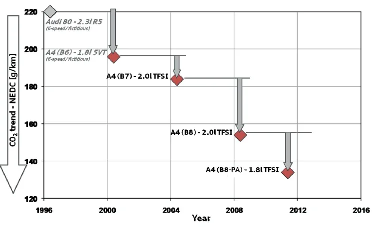
|
Fig. 3: | Trend in CO2 emissions of Audi turbocharged petrol engines (B-class 1995-2012) |
2 The third generation 1.8l EA888 engine
As already described, in the summer of 2011 Audi put into production the third
generation of its four-cylinder inline TFSI engine. The first of this new generation is
the 1.8l EA888 TFSI in the new Audi A4. The 1.8l TFSI once again incorporates a
large number of new and innovative technologies, some of which are being deployed
for the first time in a mass production engine.
2.1 Base engine – Optimised friction and thermal management
Many new, efficiency-enhancing measures have been implemented even in the base
engine model. As shown in Figure 4, the main components relevant to friction were
completely redesigned. In addition to a conventional optimisation of the piston-liner
friction, the balance shafts were in part mounted on roller bearings. Also, the
crankshaft bearings were reduced in size and, more specifically, adapted to the load
demands of the 1.8l TFSI engine. The complete oil circuit was also revised, and the
pressure and volumetric flow controlled oil pump was reconfigured. For the first time
switchable piston cooling nozzles are also employed, in order to realise additional
20th Aachen Colloquium Automobile and Engine Technology 2011 5
potential particularly during the heat-up phase and under low loads. This represents a
further implementation of variability in the crank drive as in other areas.
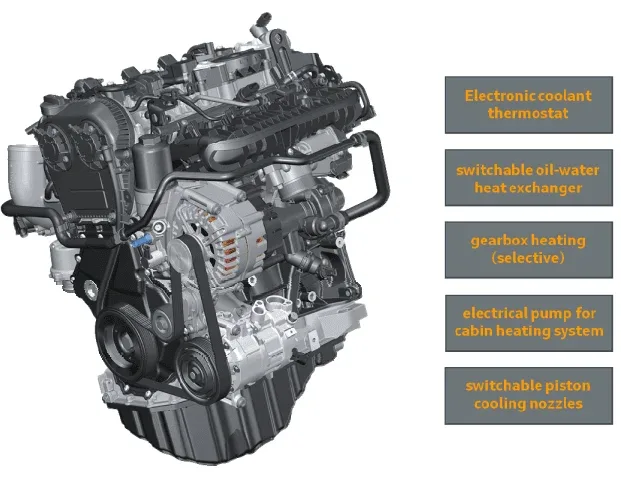
Fig. 4: 1.8l EA888 Gen.3 – Measures to optimize friction
Further significant advantages in terms of fuel consumption were achieved by means
of an actively controlled thermal management system (Figure 5). One of the technical
highlights of this is the first use of an electronic coolant thermostat (Figure 6). This
makes it possible to leave the coolant standing after the engine starts, as a result of
which the engine warms up much more rapidly. Once a modelled component
temperature is reached, a first rotary slide opens a small cross-section, causing a
mini-volumetric flow to slowly move the coolant. The engine continues to warm up
much faster than at the otherwise normally much higher volumetric flows.
As the engine continues to warm up, in a likewise temperature-controlled sequence
first the oil/water heat exchanger is activated by way of the electronic coolant
thermostat and then the gear oil heat exchanger is activated by an additional
switching valve. Only when the specified coolant temperature of 107°C has been
reached does the coolant thermostat mix-in cold water from the main cooler, so
regulating the coolant temperature under map control to the specified temperature.
As well as controlling the heat-up process in order to optimise fuel consumption, the
coolant thermostat also enables demand-based engine temperature control. As
already mentioned, in the lower part load range a high, fuel consumption optimised
coolant temperature of 107°C is set. Under higher loads the coolant temperature is
gradually reduced based on map control. Under full load, the electronic coolant
thermostat can very rapidly lower the coolant temperature down to 85°C, thereby
reducing the tendency to knock and so likewise delivering benefits in terms of
efficiency. This means that, ultimately, the optimum coolant temperature to achieve
maximum efficiency can be set for any operating point.
The thermal management system in the Audi A4 is rounded off by an autonomous
heating system. A switching valve and an electric heating pump enable the heating
circuit to be deactivated or, as necessary, allow heating mode to be activated while
there is still coolant standing in the engine block or if the volumetric flow by the main
coolant pump is low. In the latter case the heat is drawn only from the cylinder head
with the integrated exhaust manifold. In both cases, the engine block in particular –
and thus the piston liner assembly – heats up much faster than without the thermal
management measures, resulting in further fuel consumption benefits.
|
Fig. 7: |
1.8l EA888 Gen.3 – Temperature curve in the NEDC with autonomous heating compared to 1.8l EA888 Gen.2 |
Figure 7 shows the temperature curve of the third generation 1.8l EA888 in the
NEDC with autonomous heating compared to the second generation 1.8l EA888. The
more rapid rise in coolant temperature and the higher operating temperature of the
third generation engine are clear to see. Overall, enhancements to the thermal
management system helped cut the engine’s CO2 emissions in the NEDC by
approximately 2.5 g.
8 20th Aachen Colloquium Automobile and Engine Technology 2011
2.2 Combustion process and Thermodynamics
For the new third-generation EA888 engine the tried and proven TFSI combustion
process has been optimized further in a wide variety of aspects, both to further
improve robustness in terms of knocking and spark advance at mean pressures
increased up to 22 bar and to optimize combustion stability under the changed
conditions due to the integrated exhaust manifold in terms of residual gas behavior
and air ratio. In addition to this, the charge motion induced by the inlet port without
the tumble flap activated has been increased once again. As a result of the
optimized, slightly retracted position of the high-pressure injector, mixture
homogenization has been further improved, and at the same time a positive side-effect has been achieved in the reduction of the temperature load on the injector.
To achieve the required increase in power output allied to much improved
spontaneity and optimised full load fuel efficiency, the Audi valvelift system (twostage valve lift change-over of the exhaust camshaft) familiar from the 2.0l TFSI
predecessor engine was adopted and for the first time combined with a camshaft
adjuster on the exhaust side to provide maximum degrees of freedom in controlling
the charge cycle.
Fig. 8: 1.8l EA888 Gen.3 – Dual injection system
The third generation EA888 also for the first time features a dual fuel injection system
(Figure 8). Alongside a high-pressure direct-injection system with system pressure
increased from 150 to 200 bar, a low-pressure injection system has also been
20th Aachen Colloquium Automobile and Engine Technology 2011 9
integrated into the VTS (Variable Tumble System) flange which injects into the upper
area of the inlet ducts. Using the dual injection system allows the optimum fuel
injection to be selected in every load range (intake manifold injection under low loads
and direct injection under medium and high loads), so enabling a further reduction in
CO2 emissions while at the same time complying with future emission limits.
Fig. 9: 1.8l EA888 Gen.3 – Combustion process / Thermodynamics
As shown in Figure 9, alongside the usual variability in terms of ignition and injection
timing and wastegate control, the third generation EA888 now exhibits seven
additional variabilities so as to ensure optimum charge motion and mixture
preparation, as well as attaining the ideal mixture of air, fuel and residual gas, at
every operating point, thereby maximising thermodynamic efficiency. Implementing
an engine with so many degrees of freedom poses an extreme challenge to the
applications engineers.
2.3 Turbocharging and full-load performance
Alongside direct fuel injection, turbocharging is the core technology of the TFSI
technology. In this context, too, a wide range of new technologies have been
deployed alongside detail optimisation measures. Figure 10 shows the principal full
load control components.
10 20th Aachen Colloquium Automobile and Engine Technology 2011
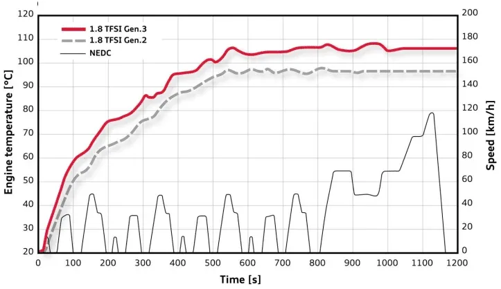
Fig. 10: 1.8l EA888 Gen.3 – Turbocharging control components
A technical ‘highlight’ in this respect is without doubt the cylinder head with integrated
exhaust manifold (Figure 11), put into production by Audi for the first time in the third
generation EA888.
Fig. 11: 1.8l EA888 Gen.3 – Cylinder head with integrated exhaust manifold
Integrating the exhaust manifold into the water-cooled cylinder head means that the
exhaust gas is cooled on its way to the turbocharger. In combination with a cast steel
20th Aachen Colloquium Automobile and Engine Technology 2011 11
turbocharger, the engine can thus be run in the upper load range at approximately
100°K higher combustion temperatures, which means thermodynamic efficiency can
be significantly improved and consumption under high load can be greatly reduced.
Achieving a thermodynamically and thermomechanically optimised package of gas
ducts and cooling ducts posed a particular challenge during the development of the
cylinder head, especially with regard to production feasibility and castability on a
mass production scale.
With regard to coolant transport, a strategy of ‘keeping the coolant flow under control
at all times’ was pursued right from the start. The coolant flows are adjusted and
divided by way of defined cross-sections in the cylinder head gasket, with 75% of the
total coolant flow being routed via the integrated exhaust manifold. The remaining
25% bypasses the integrated exhaust manifold, flowing directly from the cylinder
block into the cylinder head. High flow speeds in the coolant ducts permit greater
heat transport and thus intensive cooling, particularly of the critical web areas, and so
safely prevent local boiling of the coolant.
Fig. 12: 1.8l EA888 Gen.3 – Combined simulation “CCM+” (CFD and FEM)
From the very beginning, development work was supported by the intensive use of
CFD calculations. To be able to simulate the complex effects inside the integrated
exhaust manifold with sufficient accuracy, alongside established CFD and FEM
methods a number of new simulation methods also had to be developed, enabling
CFD and FEM calculations to be combined and optimisation measures to be
interlinked.
First, classic CFD simulations were used to produce the basic design of the gas and
water cores and combined with FEM methods to thermomechanically optimise the
12 20th Aachen Colloquium Automobile and Engine Technology 2011
cylinder head. As there is intensive coupling between the exhaust gas and cooling
water flows and heat transport in the aluminium within a very tight space – that is to
say, involving extreme temperature gradients – in this project all three areas (gas,
water, aluminium) were also calculated in a single simulation model for the first time
(Figure 12, left). This methodology enables retroactive effects of the component
temperatures on the fluid temperatures and the resultant heat flows to be simulated
more accurately.
The development of the integrated exhaust manifold cylinder head revealed that, as
well as the stationary cooling design, the load cycles involving negative load and
speed changes are also a key factor. Immediately after such a change of operating
state, firstly the large amount of heat stored in the material is discharged into the
cooling water and, secondly, the cooling water volumetric flow and pressure
decrease dramatically due to the slow water pump speed caused by the low engine
revs. The hot water jacket areas are particularly at risk of boiling in this context, which
in the long term may result in harm to the cooling water.
Extreme cases of such load cycles, as well as rapid shutdowns, were analysed both
on the test rig and by simulation. In the final integrated exhaust manifold
configuration, from an integral viewpoint a comparable level to the predecessor
engine was attained in terms of short-time boiling intensity (Figure 12, right). This
simulation methodology, too, was deployed for the first time in the course of the
integrated exhaust manifold development.
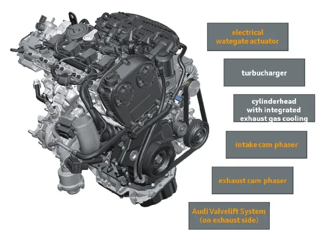
Fig. 13: 1.8l EA888 Gen.3 – Gas transport in integrated exhaust manifold and
turbocharger
20th Aachen Colloquium Automobile and Engine Technology 2011 13
Extensive CFD simulations and measurements were also carried out on the fired
engine in order to configure the gas ducts. To prevent interaction between the
cylinders in the lower and mid engine speed ranges especially, a long ignition
sequence separation, extending into the turbocharger, was implemented. At the
same time, the gas ducts were configured such that the flow takes place with as little
loss as possible, and is always routed directly towards the turbine (Fig. 13).
Ultimately, this reduced the flow losses and push-out work, as well as lowering the
residual gas content in the cylinders, across the entire engine speed range. The
impulse energy onto the turbine was also increased. Overall, despite the restrictions
imposed by the package, the integrated exhaust manifold configuration delivers
almost identical performance to that of an external exhaust manifold in terms of flow
technics and gas dynamics.
The turbocharging system is an entirely newly developed mono-scroll turbocharger
(Figure 14). The aim of the turbocharger design was to combine good low-end torque
with maximum power output and very high performance. The basis for this design
was the RHF4 turbocharger from IHI, with various improvements made to the rotor
assembly, the spirals, the housings and to all the flow-carrying parts and
components.
Fig. 14: 1.8l EA888 Gen.3 – Turbocharger with electric wastegate
The turbocharger turbine housing is made of cast steel 1.4837, and so permits a
turbine inlet temperature of 980°C. For the first time at this high exhaust gas
14 20th Aachen Colloquium Automobile and Engine Technology 2011
temperature, it was possible to fabricate the turbine wheel in Inconel 713 C instead of
MAR. The compressor rotor is milled from a solid block, which delivers advantages
such as greater high-speed strength and better acoustics.
The third generation 1.8l EA888 features the first use by Audi of an electric
wastegate actuator. This enables even faster and more precise control of the
wastegate than the previously used actuator with a pressure cell. Active opening of
the wastegate under part load enables the base charge pressure to be lowered. This
results in additional savings in fuel consumption both in the NEDC and in customer
applications. The active opening of the wastegate also permits faster catalytic
converter heat-up, resulting in lower cold-start emissions.
For the first time at Audi the oxygen sensor has been positioned ahead of the
turbocharger turbine. This allows for a considerably earlier dew point end, and thus
early enabling of lambda control after the engine starts, as well as providing good
individual cylinder recognition.
Extensive CAE optimisation work was carried out on both the turbine and compressor
sides. Figure 15 shows both CFD simulation models in one view. On the turbine side,
the CFD simulations in the complete system are analysed with the integrated exhaust
manifold gas routing in the cylinder head, the turbine housing (including impeller), the
wastegate, the oxygen sensor upstream of the turbine and the exhaust system
through to downstream of the close-coupled main catalytic converter. The aims here
were to optimise the integrated exhaust manifold gas routing in conjunction with the
turbine inlet, the flow to the oxygen sensor, the wastegate design, and to ensure a
very good flow to the catalytic converter.
Fig. 15: 1.8l EA888 Gen.3 – CFD simulations of the turbocharger system
20th Aachen Colloquium Automobile and Engine Technology 2011 15
On the compressor side the CFD model includes the air induction, the compressor
including all inlet points (e.g. from the crankcase ventilation) as well as the dump
valve and the charge air duct. The aim was firstly to develop gas flow to and from the
compressor that was as loss-free as possible and neutral with regard to the
performance of the compressor, and secondly to find the best possible position for
the inlet points and the recirculation valve. In this context the simulations identified
considerable potential both with regard to reduce pressure losses and in terms of
compressor efficiency.
On completion of the extensive optimisation work, the turbocharger of the third
generation 1.8l EA888 engine exhibited better low-end torque, and in particular faster
responsiveness, than other turbocharger design concepts currently on the market
and in development, while attaining the same power and torque data. It thus
represents the current benchmark in turbocharger technology.
The outstanding result is also illustrated again in Figure 16, in which the full-load
torque and dynamic torque curve of the new third generation 1.8l EA888 engine are
compared against the data of its predecessor and against the second generation 2.0l
EA888. The significant advantages over the second generation 1.8l engine are clear
to see, as is the fact that the third generation 1.8l engine is practically equal to the
larger-capacity second generation 2.0l both in terms of torque level and dynamic
torque curve.
Fig. 16: 1.8l EA888 Gen.3 – Full-load torque and dynamics compared to 1.8l
EA888 Gen.2 and 2.0l EA888 Gen.2
16 20th Aachen Colloquium Automobile and Engine Technology 2011
For the new Audi A4 in the 125/132 kW class, this ultimately made it possible to
replace the existing 2.0l engine with the new 1.8l unit, and so not only realise the
aforementioned improvements in thermodynamic and mechanical efficiency but also
to achieve a further improvement in CO2 emissions of 6 to 7 g in the NEDC by means
of downsizing, without customers having to accept compromises in terms of
performance.
3 Future developments in TFSI technology
The questions for the future will be how the direct-injection petrol engine will continue
to be developed, and what potential it offers in particular with regard to further
reductions in CO2 emissions.
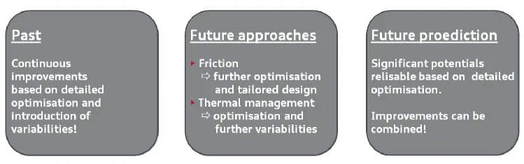
3.1 Base engine – Optimised friction and thermal management
As already demonstrated, fuel consumption improvements were achieved in the past
in relation to optimisation of friction and thermal management based on continuous
detail optimisation and the introduction of variability.
|
Fig. 17: | Further development of TFSI technology – Friction and thermal management |
There remains significant potential to be realised in future. Detail optimisation in
relation to engine friction will mean that engines will be tailored ever more precisely to
their specific applications. In terms of thermal management, although the early
approaches implemented have realised considerable potential, there still remains
significant potential for improvement. This is, however, conditional on the introduction
of further variability. The improvements in fuel consumption brought by optimising
friction and by thermal management fundamentally offer the benefit of reducing
losses while having little cross-effect on other optimisation measures, so that the
respective gains can be combined almost completely.
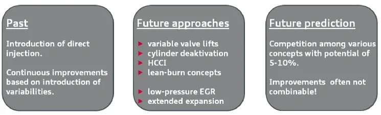
3.2 Combustion process and thermodynamics
With regard to the combustion process and thermodynamics, improvements in the
past were achieved thanks to the introduction of direct fuel injection and large
20th Aachen Colloquium Automobile and Engine Technology 2011 17
numbers of variabilities, as well as by stretching the operating parameters to their
limits. In conjunction with the conventional =1 combustion processes, however, the
existing potential in this regard has now been largely exhausted.
But for some considerable time there have been new technical ideas in circulation
which seek to realise further potential based on new combustion methods or cylinder
deactivation. But the lean-burn methods, homogeneous charge compression ignition
(HCCI), variable valve lift control or cylinder shut-off, all target the lower part-load
range and utilise similar physical effects (derestriction, reduction of heat losses).
Consequently, it is in most cases pointless to combine the methods as, once a
technology has delivered its advantages, few further benefits are achievable.
|
Fig. 18: | Further development of TFSI technology – Combustion process and thermodynamics |
Low-pressure EGR or methods involving extended expansion (Miller/Atkinson Cycle)
tend to promise more in the way of efficiency advantages in the mid and upper load
ranges. These two methods also utilise similar physical principles, so ultimately once
again it only makes sense to apply one of the two. Combining them would deliver
very little additional gain. The disadvantages of both methods, however, are that they
require an increased charge pressure and that they reduce the full-load torque and
nominal power output. To compensate for this, in order to avoid compromises in
terms of performance, turbocharger design concepts involving increased charge
pressure supply are required.
So, all in all, there remains significant potential for reducing consumption by
thermodynamics-related measures as in other areas. The potential is estimated at 5
to 10 percent, and will doubtless be gradually realised in future.
However, one point needs to be considered in this context. In the past, car-makers
had great difficulty in introducing new combustion processes, as – in addition to their
advantages – they in most cases also entailed a wide range of disadvantages
relating to exhaust gas after treatment or combustion stability and smooth running,
and as a consequence were mostly withdrawn from the market again after a short
time. In this light, it is doubtless more likely that there will be an evolution of the
current =1 combustion processes rather than any revolutionary introduction of new
methods.
18 20th Aachen Colloquium Automobile and Engine Technology 2011
3.3 Turbocharging
The core technology in the rapid developments seen over recent years was without
doubt turbocharging – also of course in conjunction with the introduction of variability
enabling the charge cycle to be controlled ever more optimally. On the other hand,
due to that rapid past development some limits have today already been reached.
As a consequence of the improvements in torque of TFSI engines, in many vehicle
design concepts the gear ratios have been extended so far in recent years that
further extension would bring no benefit, so little further downspeeding potential
exists. For mono-turbocharger concepts, in Audi’s view a specific torque of
approximately 175 Nm/l today likewise represents a useful limit, in order still to
safeguard adequate low-end and starting-off torque and dynamic responsiveness,
thereby ensuring good driveability in all situations.
Consequently, in Audi’s view the key challenges of the future in terms of
turbocharging concepts are to improve starting-off and low-end torque and dynamic
torque build-up – that is to say, ultimately, the rapid availability of high charge
pressures even from very low engine speeds. In this respect, too, there are already a
number of technical ideas in circulation for the future development of turbocharging
technology.
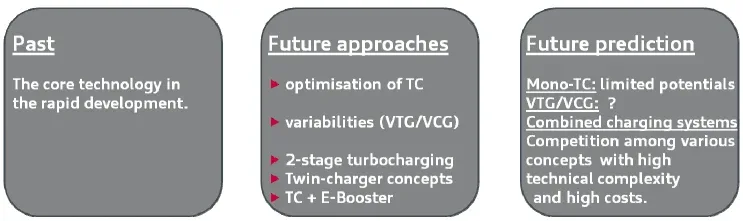
Fig. 19: Further development of TFSI technology – Turbocharging
However, the turbochargers themselves are today for the most part fully optimised,
and as such offer only limited potential. Turbocharger developers are investigating a
number of technologies in terms of aerodynamic or mechanical optimisation, but at
present they are frequently revealing only minor potential improvements at still very
high cost, so their application in mass production would appear unlikely at any time in
the near future.
Research has likewise been ongoing for more than 10 years with regard to variability
on the turbine and compressor side, though to date only in a few number of cases
they have been turned into production applications, as they often offer few
advantages in the totality of their properties and, again, entail relatively high cost.
The third possibility to advance turbocharger technology and the associated concepts
– and the one doubtless offering the highest potential in technical terms – is a
20th Aachen Colloquium Automobile and Engine Technology 2011 19
combination of charging systems, such as combining two turbochargers or one
turbocharger with a mechanically or electrically driven compressor. In purely
thermodynamic terms, these concepts offer considerable advantages, with no major
functional cross-effects – provided the overall systems are configured appropriately.
However, the integration of the overall concepts into the engine and vehicle package
demands considerable effort and expense, and – for small models in particular – is
often difficult or in some cases even impossible. Moreover, combination
turbocharging concepts are very costly, both in terms of the turbocharger
components themselves and also frequently in terms of peripheral on-board
components.
But since the greatest potential in future is expected to be realised by advances in
turbocharging technologies, there will no doubt be fierce competition among the
various concepts, and those offering the best cost/benefit ratio will win through.
However, as turbocharging increases further, and thus more downsizing is
implemented, one problem will arise. The ever greater knock limitation, reduced
compression ratios and increasing charge cycle losses will almost certainly lead to a
rise in consumption under high load. This may result in increased consumption in
customer applications, depending on the vehicle model and driving habits, where
extreme downsizing concepts are implemented. Consequently, highly charged
concepts will necessitate additional measures especially in order to cut fuel
consumption under high load. In view of this, a combination with some of the
combustion methods presented in the previous section appears to be a most useful
solution.
4 Summary and Outlook
With the introduction of TFSI technology in 2004, Audi launched a new era in petrol
engine development. No engine technology other than TFSI has delivered such a
boost to performance and fuel efficiency in such a short time, and no other engine
technology has established itself on the market in such a short time (just five years!),
practically eliminating all other competing technologies in the process.
With the aid of turbocharging and TFSI technologies, the CO2 emissions of Audi and
VW Group models have been significantly reduced over the last 15 years, while
performance has been greatly improved.
The new 1.8l TFSI in 2011 marks the launch of the third generation of the successful
TFSI technology from Audi. Alongside extensive modification and optimisation of the
engine, in this third generation of the four-cylinder inline TFSI engines Audi has once
again introduced a wide range of new and innovative technologies – some of them
being put into mass production for the first time.
The technical highlights of the new engine generation:
Electronic coolant thermostat
20 20th Aachen Colloquium Automobile and Engine Technology 2011
Cylinder head with integrated exhaust manifold
Electric wastegate actuator
Dual injection system
With the third generation of TFSI engines, significant progress has once again been
made compared with the already very well positioned second generation of the
EA888 engine series, thus further strengthening the outstanding position of the fourcylinder inline TFSI engine range in the competitive environment. The new 1.8l
EA888 TFSI engine without doubt represents a further milestone in Audi’s downsizing
and downspeeding strategy.
TFSI technology will continue to offer wide-ranging potential in future, particularly with
regard to cutting CO2 emissions. Key technologies in this, from Audi’s viewpoint, will
be advances in turbocharging technology and the introduction of new combustion
methods.
20th Aachen Colloquium Automobile and Engine Technology 2011 21
5 References
[1] Krebs, R.; Böhme, J.; Dornhöfer, R.; Wurms, R.; Friedmann, K.; Helbig, J.;
Hatz, W.
Der neue AUDI 2,0T FSI Motor – Der erste direkteinspritzende Turbo-Ottomotor
bei AUDI [The new Audi 2.0T FSI engine – the first direct-injection turbocharged
petrol engine from Audi]
25th Vienna Engine Symposium 2004, Vienna 2004
[2] Wurms, R.; Kuhn, M.; Zeilbeck, A.; Adam, S.; Krebs, R.; Hatz, W.
Die Audi Turbo FSI Technologie [The Audi turbo FSI technology]
13th Aachen Colloquium on Vehicle and Engine Technology, Aachen 2004
[3] Böhme, J.; Hatz, W.; Eiser, A.; Dornhöfer, R.; Ehret, W.; Wurms, R.
Der neue R4-1,8l T-FSI-Motor von AUDI [The new four-cylinder inline 1.8l TFSI
engine from Audi]
15th Aachen Colloquium – Vehicle and Engine Technology, Aachen 2006
[4] Dornhöfer, R.; Hatz, W.; Eiser, A.; Böhme, J.; Adam, S.; Unselt, F.; Cerulla, S.;
Zimmer, M.; Friedmann, K.; Uhl, W.
Der neue R4 2,0l 4V TFSI-Motor im AUDI S3 [The new four-cylinder inline 2.0l
4V TFSI engine in the Audi S3]
11th Supercharging Conference, Dresden 2006
[5] Eiglmeier, C.; Pfalzgraf, B.; Helbig, J.; Adam, S.; Grigo, M.; Dornhöfer, R.;
Eiser, A.
Der neue R4 – 2,0l TFSI SULEV/PZEV-Motor von AUDI [The new four-cylinder
inline 2.0l TFSI SULEV/PZEV engine from Audi]
16th Aachen Colloquium on Vehicle and Engine Technology, Aachen 2007
[6] Wurms, R.; Budack, R.; Böhme, J.; Dornhöfer, R.; Eiser, A.; Hatz, W.
Der neue 2.0L-TFSI mit Audi valvelift system für den Audi A4 – die nächste
Generation der Audi Turbo-FSI-Technologie [The new 2.0l TFSI with Audi
valvelift system for the Audi A4 – the next generation of Audi turbo FSI
technology]
17th Aachen Colloquium – Vehicle and Engine Technology, Aachen 2008
[7] Ballauf, J.; Hatz, W.; Eiser, A.; Dornhöfer, R.; Grigo, M.; Ewald, A.; Stichlmeir,
M.
Audi 2.0l TFSI flexible fuel
12th Conference on The Working Process of the Combustion Engine, Technical
University of Graz, 24/25 September 2009
[8] Heiduk, T.; Dornhöfer, R.; Eiser, A.; Grigo, M.; Pelzer, A.; Wurms, R.
“Die neue Motorgeneration des R4 TFSI von Audi” [The new four-cylinder inline
TFSI engine generation from Audi]
32nd Vienna Engine Symposium 2011, Vienna 2011
22 20th Aachen Colloquium Automobile and Engine Technology 2011