
Subaru Legacy Transmission
Subaru Legacy Transmission sensors check
A: INSPECTION
1) Remove the air intake chamber and duct.
2) Disconnect the transmission connector.
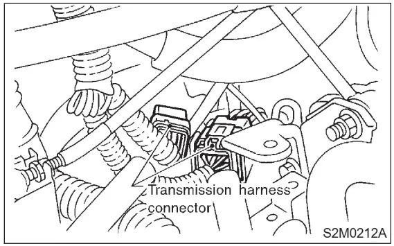
Legacy Transmission
3) Check each sensor, solenoid and ground system for short circuits.
(A) Torque converter turbine speed sensor
(B) Vehicle speed sensor 2 (Front)
(C) Vehicle speed sensor 1 (Rear)
(D) ATF temperature sensor
(E) Duty solenoid A (Line pressure)
(F) Duty solenoid B (Lock-up)
(G) Duty solenoid C (Transfer)
(H) Duty solenoid D (2-4 brake)
(I) Shift solenoid 1
(J) Shift solenoid 2
(K) 2-4 brake timing solenoid
(L) Low clutch timing solenoid
(M) Transmission connector
1. EVALUATION
NOTE:
If part is faulty, its resistance value will be different
from the standard value indicated above.
4. Shift Solenoid, Duty Solenoid and Valve
A: REMOVAL
1) Clean transmission exterior.
2) Drain ATF completely.
NOTE:
Tighten ATF drain plug after draining ATF.
Tightening torque:
25±2 N·m (2.5±0.2 kg-m, 18.1±1.4 ft-lb)
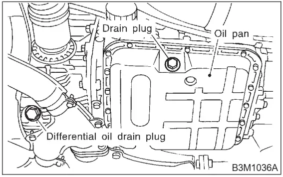
3) Remove oil pan.
NOTE:
Drain oil into a container.
4) Disconnect solenoid and sensor connectors.
Remove connectors from clip and disconnect connectors at 8 places.
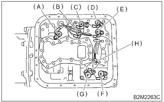
(A) Lock-up duty solenoid (Blue)
(B) Low clutch timing solenoid (Gray)
(C) Line pressure duty solenoid (Red)
(D) Shift solenoid 2 (Yellow)
(E) Shift solenoid 1 (Green)
(F) 2-4 brake timing solenoid (Black)
(G) 2-4 brake duty solenoid (Red)
(H) ATF temperature sensor
5) Remove control valve body.
CAUTION:
When removing control valve body, be careful
not to interfere with transfer duty solenoid C
wiring.
NOTE:Be careful because oil flows from valve body.
6) Remove oil strainer.
NOTE:
Be careful because oil flows from oil strainer.

7) Remove solenoids and duty solenoids.
(A) Lock-up duty solenoid (Blue)
(B) Low clutch timing solenoid (Gray)
(C) Line pressure duty solenoid (Red)
(D) Shift solenoid 2 (Yellow)
(E) Shift solenoid 1 (Green)
(F) 2-4 brake timing solenoid (Black)
(G) 2-4 brake duty solenoid (Red)
(H) ATF temperature sensor
B: INSTALLATION
1) Install 7 solenoids and ATF temperature sensor.
Tightening torque:
T: 8±1 N·m (0.8±0.1 kg-m, 5.8±0.7 ft-lb)
(A) Lock-up duty solenoid (Blue)
(B) Low clutch timing solenoid (Gray)
(C) Line pressure duty solenoid (Red)
(D) Shift solenoid 2 (Yellow)
(E) Shift solenoid 1 (Green)
(F) 2-4 brake timing solenoids (Black)
(G) 2-4 brake-duty solenoids (Red)
(H) ATF temperature sensor
2) Install oil strainer.
Tightening torque:
8±1 N·m (0.8±0.1 kg-m, 5.8±0.7 ft-lb)
(A) Short bolt
(B) Middle bolt
(C) Long bolt
3) Install valve body to transmission case.
(1) Temporarily tighten the valve body on the
transmission case.
CAUTION:
When installing control valve body, be careful
not to interfere with transfer duty solenoid wiring (brown).
NOTE:
Align manual valve connections.
(A) Short bolts
(B) Long bolts
(2) Tighten the valve body to the specified
torque.
Tightening torque:
8±1 N·m (0.8±0.1 kg-m, 5.8±0.7 ft-lb)
4) Connect harness connectors at 8 places.
Connect connectors of same color, and secure
connectors to valve body using clips.
(A) Lock-up duty solenoid (Blue)
(B) Low clutch timing solenoid (Gray)
(C) Line pressure duty solenoid (Red)
(D) Shift solenoid 2 (Yellow)
(E) Shift solenoid 1 (Green)
(F) 2-4 brake timing solenoid (Black)
(G) 2-4 brake duty solenoid (Red)
(H) ATF temperature sensor
5) Apply proper amount of liquid gasket (THREE
BOND Part No. 1217B) to the entire oil pan mating surface.
6) Install oil pan.
Tightening torque:
4.9±0.5 N·m (0.50±0.05 kg-m, 3.6±0.4 ft-lb)

7) Fill ATF up to the middle of the “COLD” side on
level gauge by using the gauge hole.
Recommended fluid:
Dexron IIE or Dexron III type automatic
transmission fluid
Fluid capacity:
9.3 — 9.6 (9.8 — 10.1 US qt, 8.2 — 8.4
Imp qt)
8) Run the vehicle until the ATF temperature rises
from 60 to 80°C (140 to 176°F) and check the ATF
level of the “HOT” side on level gauge.
HOME