
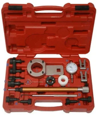
VAG TIMING TOOL KIT – 1.8/2.0 4v TFSi & 2.0L TURBO TIMING SET
Introduction:
The kit consists of 11 main components which
include the tools recommended by the
manufacturer to set No.1 cylinder at TDC. It is
important that the correct process is followed
when setting up these engines.
| 2.0L Turbo Timing Set Applicable to VAG vehicles with a 2.0L (turbo) engine T10355: Used for counter-holding the vibration damper when loosening or tightening the center bolt of the Crankshaft T10368: Used when removing and installing Lower Timing Chain Cover T40196: Used for sliding pieces on Camshaft on 2.0L 4V Turbo engines |
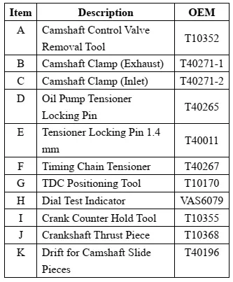
| Instruction: Preparation and Precautions: Raise the front of the vehicle and remove the front wheels and inner wheel arches as required. Remove the engine under shield, top cover, air intake, auxiliary drive belt(s). Ensure the engine is at TDC No.1 cyl. Ensure the chain tensioner is fully retracted and held in the retracted position using the pin provided. Component Description: 1. Camshaft Control Valve Removal Tool This tool is double sided and therefore 2 tools in one unit. (A) enables the removal and refitting of the Camshaft Control Valve prior to timing chain removal or engine disassembly. After removal of the electrical connections from the Cam Control Valve solenoid remove the timing cover and using the appropriate face of the tool on a suitable wrench unscrew the Control Valve in a clockwise direction as shown in (Fig.1). |
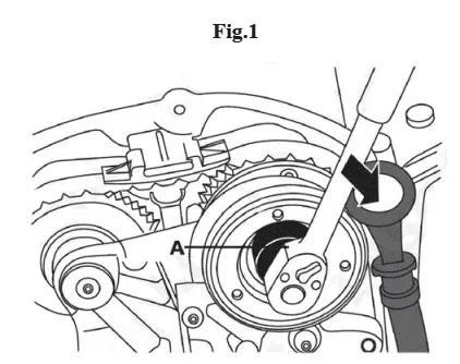
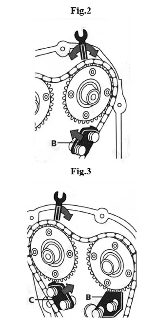
| 2. Camshaft Clamp (Exhaust & Inlet) (B) and (C) are designed primarily for use on the later Generation 3 engines and are designed to lock the camshaft pulleys in position as shown in (Fig.2) and (Fig.3). Once the engine is set at TDC No.1 and the cam pulley marks are aligned fit the exhaust clamp first. Use an open ended wrench to gently turn the camshaft to allow the clamp to fully engage with the sprocket teeth. Fitting of the inlet camshaft clamp is as shown in (Fig.3) |
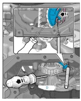
| 3. Oil Pump Tensioner Locking Pin (D) is the tensioner locking pin for the oil pump drive chain tensioner on the Generation 3 engines. It is required to lock the tensioner in its fully retracted position when removing the oil pump drive chain. |
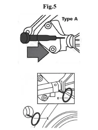
| 4. Tensioner Locking Pin 1.4 mm/Timing Chain Tensioner Both (E) and (F) are tensioner locking tools for the main cam chain tensioner. The tensioner type dictates which locking device is used. Both tensioners can be locked prior to removal of the lower chain cover via an access window in the chain cover as shown in (Fig.5) and (Fig.6). 4-1 Type A shown below use (E), for type A use a small screwdriver inserted in to the tensioner in the direction shown to release the plunger and push the tensioner plunger fully back, insert (E) to lock the plunger as shown in (Fig.5). |
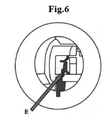
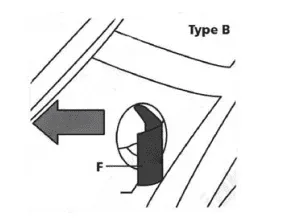
| 4-2 Type B shown in (Fig.6) uses locking tool (F). Release the tensioner retaining clip and push the plunger back to its fully retracted position. Insert (F) as shown to lock the tensioner. |
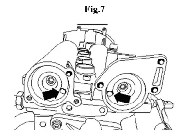
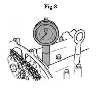
| 5-1 (G) is used, in conjunction with a suitable Dial Gauge Metric (8 mm deflection) for use with (G), to locate the TDC No.1 cylinder position. Assemble (G) and the dial gauge together and secure the dial gauge in place using the thumb screw on the positioning tool. Screw the (B) into the thread of spark plug hole of No.1 cylinder and turn the engine over slowly, by hand, in normal direction of engine rotation. TDC position is achieved when the needle reaches its highest reading and starts to move in the opposite direction. 5-2 Check that TDC position has been achieved correctly by checking the position of the holes in the rear of the camshafts are positioned as (Fig.7). If they are not in this position turn the crankshaft one more rotation (360°) |
| 6. Dial Test Indicator Top Dead Center (TDC) measurement must be checked, this set includes TDC Adaptor (used in conjunction with a Dial Test Indicator) which enables the accurate measurement of the piston position. |
| 7. Crank Counter Hold Tool & Crankshaft Thrust Piece Removing 7-1 Remove front noise insulation. 7-2 Take electrical connector -1- for radiator fan out of bracket and unplug connector (push retainer to the rear -arrow- and press down release catch). 7-3 Move clear electrical wiring harness going to radiator fan control unit. 7-4 Unplug electrical connectors -2- and -3-. Note: Some versions have only one radiator fan. 7-5 Unscrew bolt -arrow- and remove radiator fan control unit -1-. Caution: If a used belt runs in the opposite direction when it is refitted, this can cause breakage. Before removing, mark direction of rotation of poly V-belt with chalk or felt-tip pen for re-installation. 7-6 To slacken poly V-belt turn tensioner in direction of -arrow-. 7-7 Lock tensioner with locking pin -T10060A-. 7-8 Take off poly V-belt. Caution: Risk of irreparable damage to engine. To avoid disturbing valve timing, do not turn crankshaft out of “TDC” position when vibration damper is removed. 7-9 Turn vibration damper to “TDC” position -arrow- using (I). Notch on vibration damper must align with arrow marking on cover for timing chains (bottom). 7-10 Remove bolt for vibration damper using (I). |
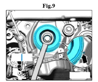
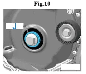
| 7-11 Detach vibration damper and fit (J) in its place. 7-12 Pull out oil seal. Installing Tightening torques 7-13 Clean contact surface and sealing surface. 7-14 Remove (J). |
| 8. Drift for Camshaft Slide Pieces Note: -Sealing surfaces at bottom of cylinder head cover and top of cylinder head must not be machined. -The camshaft bearings are integrated into the cylinder head and cylinder head cover. The timing chain must be slackened before removing the cylinder head cover. -Fit cable ties in the original positions when installing. 8-1 Perform service position 8-2 Remove engine cover panel -arrows-. 8-3 Detach air duct at bottom together with air hose. 8-4 Disconnect hose -1- from air cleaner. 8-5 Disconnect air intake hose -2-. 8-6 Pull air cleaner housing upwards -arrows-. 8-7 Plug openings in turbocharger with sealing plugs from engine bung set. 8-8 Unplug electrical connectors -arrows- at actuators for camshaft adjustment. 8-9 Detach electrical connector for Lambda probe -1- from retainer. 8-10 Release electrical connectors at ignition coils and unplug from ignition coils simultaneously. 8-11 Remove bolts for ignition coils and pull out ignition coils. 8-12 Remove actuators for camshaft adjustment -arrows-. 8-13 Disconnect crankcase breather hose -1-. 8-14 Remove bolts -arrows-, detach crankcase breather system and disconnect from crankcase breather hose -2- in direction of -arrow-. 8-15 Disconnect pipe -arrows-. 8-16 Unplug electrical connector -1- from Hall sender -G40- 8-17 Unplug connector -1- from exhaust camshaft control valve 1 -N318- and connector -2- from exhaust camshaft control valve 1 -N205-. 8-18 Unscrew bolts -arrows- and remove camshaft control valve 1 -N205- and exhaust camshaft control valve 1 -N318-. 8-19 Unscrew bolts -1 to 6- and remove timing chain cover (top). Caution: The timing valves have a left-hand thread. 8-20 Turn assembly tool -T10352/2- in direction of -arrow- to remove timing valve (left and right sides). 8-21 Remove bolts -arrows- and detach bearing saddle. 8-22 Turn vibration damper to “TDC” position -arrow- using (I). -Notch on vibration damper must align with arrow marking on cover for timing chains (bottom). -The markings -1- on the camshafts must face upwards. |
| Caution: Risk of irreparable damage to engine. Only insert assembly pins (K) in points marked in illustration. |
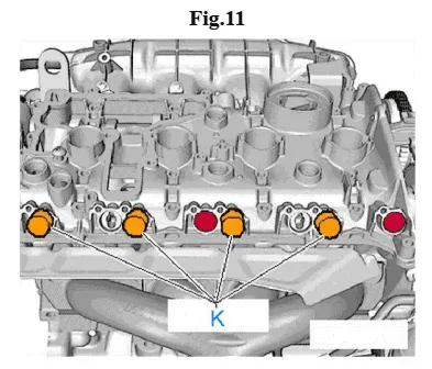
| 8-23 Insert assembly pins (K) as shown in illustration. 8-24 Turn crankshaft 2 rotations in direction of engine rotation. Note: Engine must be at “TDC” position again. 8-25 Remove assembly pins (K). |